Difference Between ERD and Class Diagram
ERD vs Class Diagram
Class Diagram
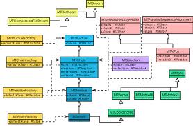
This term is used in the software field. In one of the languages of software called “UML” or “Unified Modeling Language,” there are structure diagrams which describe or show the structure of any system by the help of showing the classes of the system. These diagrams also show the operations of the classes, attributes, and relationships between different classes. These diagrams which describe the classes with the help of diagrams are called class diagrams.
In object-oriented modeling, a class diagram is the primary block for building the whole structure. Class diagrams are used for two main things:
They are used for the conceptual modeling of the systematic application.
Detailed modeling in order to translate into programming codes.
The class diagrams have many classes and subclasses, and these classes show the chief object, its interaction with other classes, and the objects which need to be programmed. These three classes are represented in the class diagrams with the help of boxes. These boxes contain three different parts. The uppermost part contains the class name, the middle one holds class attributes, and the bottom part contains the operations which can be taken by the class.
As these class diagrams are used to represent the system design, the classes are identified and sorted together to show the relationship between the objects. The representation is a static diagram which is the class diagram.
Source
http://www.google.com/search?q=class+diagram&hl=en&safe=off&prmd=ivns&tbm=isch&tbo=u&source=univ&sa=X&ei=99TxTf_-FYLOrQfj1pj6Bw&ved=0CCgQsAQ&biw=1680&bih=929
ERD (Entity Relationship Diagrams)
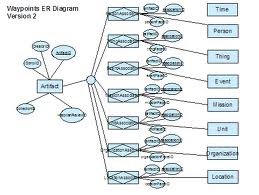
The conceptual as well as abstract representation of data in software engineering is called entity-relationship modeling. This modeling is used to model a database. It is a method by which the conceptual model of a system is produced. The diagrams produced by this method are called entity-relationship diagrams. These diagrams do not show one single entity; they show a set of entities or a set of relationships.
The sets of entities are represented by rectangles, and diamonds represent relationship sets in an ERD. A line connects when a relationship entity is participated in by an entity set. Ovals are used to represent attributes. The ERDs are used to represent the information or type of information required to be stored in a database. They are used as a requirement for analysis.
Source
http://www.google.com/search?q=ERD&hl=en&safe=off&prmd=ivns&tbm=isch&tbo=u&source=univ&sa=X&ei=ANfxTZXrGY3SrQe5nf35Bw&ved=0CFAQsAQ&biw=1680&bih=929
Summary:
The class diagrams are used to represent the main object or building block of the system. They are used to show the relationship of one class with another and also represent the attributes of the system. However, an ERD is more of a database in the form of tables. They do not show individual relationships but relationship sets as well as sets of entities. They show the type of information that needs to be stored in the database.
The class diagram and the ERD have very different graphic representations.
- Difference Between Data Mining and Data Warehousing - October 21, 2012
- Difference Between 7-Keto DHEA and DHEA - October 20, 2012
- Difference Between Tamil and Malayalam - October 18, 2012
Search DifferenceBetween.net :
 Email This Post
: If you like this article or our site. Please spread the word. Share it with your friends/family.


context diagram