Difference Between Star Connection and Delta Connection
Three-phase asynchronous cage motors can be connected to the network in two ways. In star connection, all winding ends are connected to one point. The star point is at zero potential. As a result, the engine pulls 3 times less power and the main reason why it is used in this connection to start up the powerful engines. In delta connection most commonly used for the permanent drive of the powerful engines, all the coils are connected in series.

What is Star Connection?
Linking the winding as star is the presence at one neutral point of all winding ends. The result is a figure that looks like a star, in the middle, and neutrality will always remain. Provides maximum protection against overvoltage devices. In the star connection the phase voltage is three times smaller than the interconnected one. If the winding is secondary, it is possible to apply two voltages, intermediate, between the ends of the terminals and the phase voltage between one phase and the neutral point. The star implies a smaller amount of copper used for winding, which allows saving. The coupling of primary and secondary windings with the star in the curves is equal to the linear current; the voltage of each phase is times smaller than the voltage. The latter circumstance has the consequence that winding insulation can only be considered as phase voltage and the number of phase windings can be taken in less time than would be required in the delta connection. So the star connection transformer is the cheapest. In the operational sense, one disadvantage is its uncertainty regarding the symmetry of voltage on unbalanced load. If the primary winding has a neutral wire connected to the generator, the load of one phase almost barely causes the symmetry transformer disturbance.
What is Delta Connection?
The delta connection is formed as a ring, whereby all three phases are connected to series. It is the most widespread and demanding. The connection allows circulation of free current within the ring. This is the so-called third harmonic. If at least one part of the transformer can be supplied with a delta, the current cannot move freely, which significantly disturbs the voltage. If the primary and secondary windings are connected to the triangle, all the harmonic currents that run in the closed loop, while the magnetic circuit is almost completely absent, which is very useful. The delta allows not interrupting the work of the line when there is worsening of one of the phases.
Difference Between Star and Delta Connection
Definition
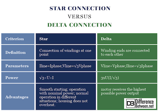
The connection of windings in star assumes their connection at one point, called zero (neutral). The zero point may be connected to the zero power point, but in all cases such a connection is not present. If there is such a connection, then this system is considered a 4-core, and if there is no such connection, then the 3-wire. In delta, the winding ends are not connected to one point but are connected to the other winding. That is, a circuit similar to the triangle appearance, and the coil connection in it goes in sequence with each other. It should be noted that the difference from the star scheme is that in the triangle scheme the system is only 3-wire, because there is no common point.
Parameters
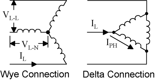
When applying a star, the phase voltages are Ua, Ub, Uc, and the phase currents are Ia, Ib, Ic. When applying a load or generator triangle circuit, Uab, Ubc, Uac, phase currents – Ia, Ib, Ic. Linear voltage values are measured between the beginnings of the phase or between the linear conductors. Linear current flows in the conductors between power supply and load. In the case of a star, the lines of the current are equal to the phase currents and the voltages are the same Uab, Ubc, Uac. In the delta diagram it is all in reverse – the phase and the linear voltages are equal and the linear currents are equal to Ia, Ib, Ic.
Power
When connecting to a star, the linear currents I and phase currents are equal, and between the phase and linear load there is relation U=√3×U, Uφ =U/√3. By comparing these formulas, we see that the forces expressed in linear quantities in combination with the stars are the same: total S=3×Sφ=3×(U/√3)×I=√3×U×I; activeP=√3×U×Ixcoscosφ; reactiveP=√3×U×I×sinφ. In delta, the linear and the phase U, the voltages are equal, and between the phase and the linear currents there is a relationship of =√3×Sxφ=3xU(I/√3); activeP=√3×U×Icoscosφ; reactiveP=√3×U×I×sinφ.
Advantages
The star has important advantages: Smooth starting the electric motor; Allows the electric motor to operate with the declared nominal power corresponding to the conductors; The electric motor will have normal operation in different situations: at high short-term overloads, with a long overload; During operation, the engine housing does not overheat. The main advantage of the delta circuit is that the electric motor receives the highest possible power output.
Star vs. Delta Connection : Comparison Chart
Summary of Star vs. Delta Connection
- In star compound the winding ends are connected to one point, and at the beginning a three-phase voltage is supplied. The focal point is at 0V potential, so each winding receives a phase voltage value (230V at the standard three-phase network).
- In delta, the windings are connected serially. Each winding is connected between the two phases of the grid, i.e. the line voltage value (400V at the standard grid). The current flowing through the supply line (line current) is 1.73 times the phase current.
- Difference Between Thermodynamics and Kinetics - June 24, 2018
- Difference Between Welding and Soldering - June 24, 2018
- Difference Between Additive Colors and Subtractive Colors - June 20, 2018
Search DifferenceBetween.net :
Leave a Response
References :
[0]Murphy, J. M. D. Thyristor Control of AC Motors, Pergamon Press, 1973.
[1]Subrahmanyam, V., Yuvarajan, S., Raamaswami, B. Analysis of commutation of a current inverter feeding an induction motor load, IEEE Trans, IA-16, 1980.
[2]Hochart, B. Power Transformer Handbook, Butterworth-Heinemann, 1987.
[3]Image credit: https://upload.wikimedia.org/wikipedia/en/thumb/c/cb/Wye_Delta_01.png/640px-Wye_Delta_01.png
[4]Image credit: https://upload.wikimedia.org/wikipedia/commons/thumb/1/18/Delta-Star_Transformation.svg/500px-Delta-Star_Transformation.svg.png