Difference Between P-N Junction Diode and Zener Diode
Diode is the simplest semiconductor element, which has one PN-connection and two terminals. It is a passive element because the current flows in one direction. The Zener diode, on the contrary, allows flowing of the reverse current.
What is P-N Junction Diode?
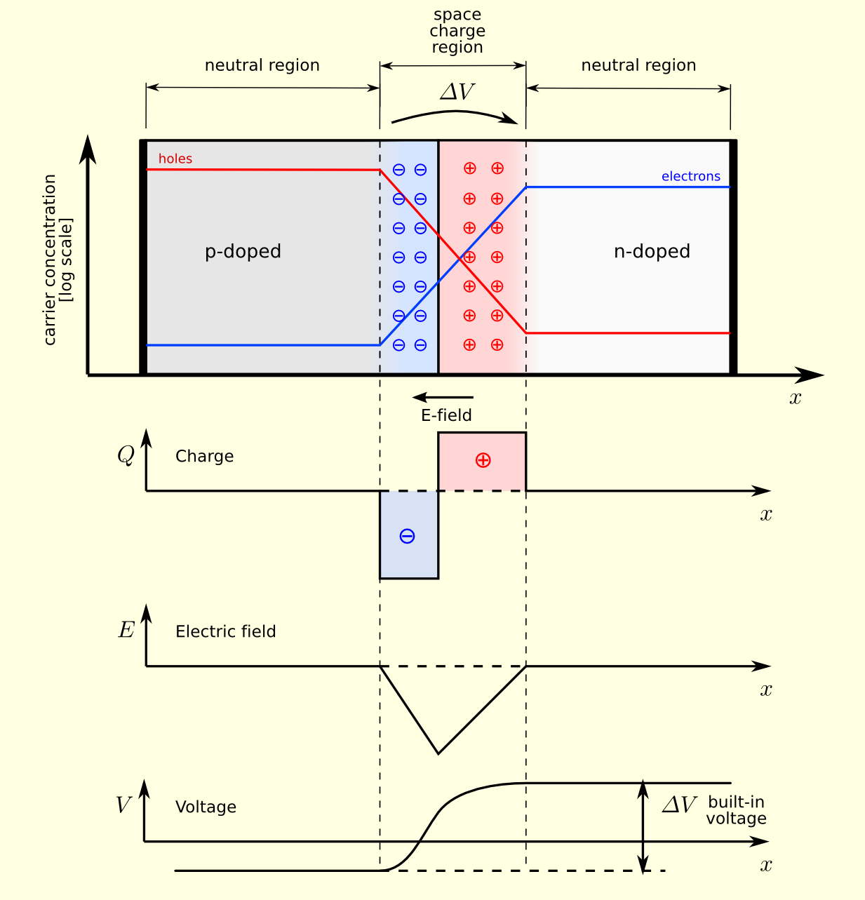
In n-type of semiconductor electrons are the main carriers of the charging, while in p-type semiconductor, the main carriers are the holes. When p-type and n-type of semiconductors are connected (which in practice is realized by a much more complicated technological process than a simple coupling), as the concentration of electrons in the n-type is much larger than that in the p-type, there is a diffusion of electrons and holes, which aims at equalizing the concentration in all parts of the semiconductor structure. Thus, electrons begin to move from more concentrated to places with less concentration, i.e. in the direction of n-type to p-type semiconductor.
Similarly this applies to holes, moving from p-type to n-type semiconductor. At the boundary of the compound, recombination occurs, i.e. filling of holes with electrons. Thus, around the boundary of the compound, a layer is formed in which abandoning of electrons and holes occurred, and which is now partly positive, and partly negative.
As around the field, a negative and positive electrification is formed, an electric field is established, which has a direction from the positive to the negative charging. That is, a field is established, whose direction is such as to oppose the further movement of electrons or holes (the direction of electrons under the influence of the field is opposite to the direction of the field).
When the field intensity increases sufficiently to prevent further electrons and holes movement, the diffuse movement ceases. Then it is said that within the p-n junction a spatial charge area is formed. The potential difference between the endpoints of this area is called a potential barrier.
The major carriers of the charge, on the both sides of the junction, are unable to pass under normal conditions (absence of a foreign field). An electric field has been established within the area of spatial load, which is strongest at the boundary of the junction. At room temperature (with the usual concentration of additive), the potential difference of this barrier is about 0.2V for silicon or about 0.6V for germanium diodes.
What is Zener Diode?
Through a non-permeable polarized p-n connection, a small reverse current of constant saturation flows. However, in real diode when the voltage of the impenetrable polarization exceeds a certain value, a sudden leakage of current occurs, so that the current eventually increases practically without any further increase in voltage.
The value of the voltage in which a sudden leakage of current arises is called a breakdown or Zener voltage. There are physically two causes that lead to breakdown of the p-n barrier. In very narrow barriers, which are produced by very high pollution of semiconductors p and n type, valence electrons can be tunneled through the barrier. This phenomenon is explained by the wave nature of the electron.
A breakdown of this type is called Zener’s breakdown, according to the researcher who first explained it. In wider barriers, minority carriers freely crossing the barrier can gain enough speed at high field strengths to break valence bonds within the barrier. In this way, additional pairs of electron holes are created, which contribute to the increase in current.
The power-voltage characteristic of the Zener diode for the bandwidth polarization area does not differ from the characteristics of a common rectifier semiconductor diode. In the field of impermeable polarization, the Zener diode penetrations usually have lower values than the penetrating voltages of ordinary semiconductor diodes, and they only work in the field of impermeable polarization.
Once the breakdown of the p-n connection happens, the current can be limited to a certain allowable value only with an external resistance, otherwise the diodes are destroyed. The values of the penetrating voltage of the Zener diode can be controlled during the production process. This makes it possible to produce diodes with a breakdown voltage of several volts up to several hundred volts.
Diodes with a breakdown voltage of less than 5V do not have a clearly pronounced breakdown voltage and have a negative temperature coefficient (the rise in temperature decreases the Zener voltage). Diodes with UZ> 5V have a positive temperature coefficient (the rise in temperature increases the Zener voltage). The Zener diodes are used as stabilizers and voltage limiters.
Difference Between P-N Junction Diode and Zener Diode
-
Definition of P-N Junction Diode and Zener Diode
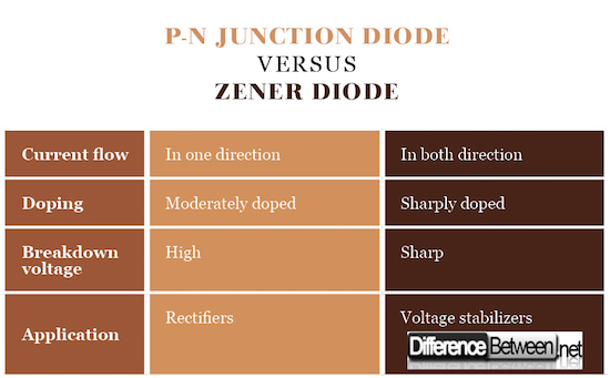
Diode is an electronic component that allows the flow of electricity in one direction without resistance (or with very little resistance) while in the opposite direction has an infinite (or at least very high) resistance. Zener diodes, on the contrary, allow reversed current flow when the Zener voltage is reached.
-
Construction of P-N Junction Diode and Zener Diode
P-n junction diode consists of two semiconductor layers (p type – anode and n type – cathode). In case of Zener diodes, the concentrations of the impurities in the semiconductors must be precisely determined (typically significantly higher than in p-n diodes) in order to obtain the desired breakdown voltage.
-
Application of P-N Junction Diode and Zener Diode
The first ones are used as rectifiers, wave shapers, switchers, voltage multipliers. Zener diodes are most often used as voltage stabilizers.
P-N Junction Diode vs. Zener Diode
Summary of P-N Junction Diode and Zener Diode
- P-n junction diodes are made of two (p and n) semiconductor layers, permitting current to flow in only in one direction, thus being used as rectifiers.
- Zener diodes are specifically doped, being able to transmit current in both directions. Most commonly used as voltage stabilizers.
- Difference Between Thermodynamics and Kinetics - June 24, 2018
- Difference Between Welding and Soldering - June 24, 2018
- Difference Between Additive Colors and Subtractive Colors - June 20, 2018
Search DifferenceBetween.net :
Leave a Response
References :
[0]Brillson, L. J. “Contacts to Semiconductors, Fundamentals and Technology”, NJ: Noyes Publications, 1993. Print
[1]Sze, S. M. “Semiconductor Devices, Physics and Technology”, 2nd Edition, NJ: John Wiley & Sons, 2001. Print
[2]Shur, M. “Introduction to Electronic Devices”, NJ: John Wiley & Sons, 1996. Print
[3]Image credit: https://commons.wikimedia.org/wiki/File:Pn-junction-equilibrium-graphs.png#/media/File:Pn-junction-equilibrium-graphs.png
[4]Image credit: https://upload.wikimedia.org/wikipedia/commons/thumb/7/7f/Zener_diode_symbol.svg/640px-Zener_diode_symbol.svg.png


