Difference Between Multimeter and Clamp Meter
When you see a faulty electrical appliance, probably the very first thing that comes to mind is a multimeter (analog or digital) because that’s the device is dominantly used to diagnose faulty electrical circuits. But, there is yet another great tool called a clamp meter which can be used to measure current but without breaking the circuit first. So, let’s look at how the two works.
What is a Multimeter?
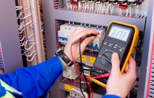
Did you ever notice any appliance at home acting all weird or not working at all? If so, then probably the first thing you can do is check the electrical circuitry for any faults. And how do you do that? You use a multimeter. So, a multimeter is an indispensable household tool for testing, diagnosing, and troubleshooting faulty electrical circuits, components, and devices. It’s a portable handheld electronic measuring tool for performing electrical testing. It can be equipped with any number of special functions, but basically a multimeter can be used to measure voltage, resistance and current. It does one simple thing: check for any fault in electrical circuits or devices.
A multimeter comes in analog and digital types. A digital multimeter, as the name suggests, displays the reading digitally meaning the values are shown on a digital display, just like a digital wristwatch. An analog multimeter, just like an analog watch, uses a needle and scale to measure current, resistance, voltage, frequency, and signal power. Some multimeters also come with auto-ranging feature but cost a little more than the general multimeters. Auto-ranging multimeters set the test range automatically. Some high-end multimeters are also used to take other readings, such as diode forward voltage, capacitance, and transistor gain.
What is a Clamp Meter?
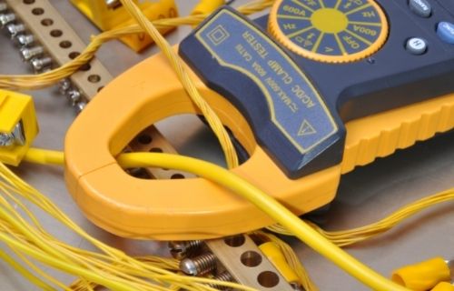
A clamp meter is yet another electrical testing tool that is clamped around a live wire to measure the current. It is a meter device that can measure current but without making any direct contact to that current. When it comes to measuring current, a multimeter is probably the most obvious choice. But a clamp meter is recommended when you test an electrical circuit without cutting the wires first. This is one of the main advantages of using a clamp meter against traditional ammeters and multimeters; you do not have to break the circuit to conduct measurements.
A clamp meter has a jaw on the top that opens when you press the liver on the side of the device. You need to place the conductor in the middle of the open jaw and release the lever, and the meter then determines the current flowing through the conductor without exposing any portion of it. You can take measurement of the line under voltage as well measure high currents. One more advantage of a clamp meter is operational safety, which basically means you can measure the current of an insulated conductor.
Difference between Multimeter and Clamp Meter
Function of Multimeter vs Clamp Meter
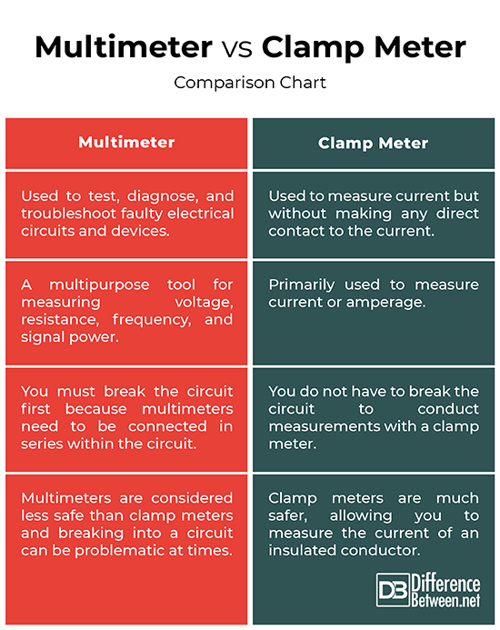
– A multimeter is like a multi-purpose electrical tool that is used to test, diagnose, and troubleshoot faulty electrical circuits and devices. It determines the electrical resistance within a circuit and also acts as a voltmeter, ohmmeter and an ammeter.
A clamp meter is yet another testing tool that is also used to measure current but without making any direct contact to that current. You do not have to break the circuit to conduct measurements with a clamp meter.
Working of Multimeter vs Clamp Meter
– A typical multimeter is inserted in series with the circuit that needs to be measured, and you need to break the circuit so that the current passes through the meter. Although, it can be difficult at times, it is the only option to measure current using a multimeter. The resistance of the meter must be set to low.
A clamp meter has a jaw on the top that opens when you press the liver on the side of the device. The conductor is placed in the middle of the open jaw and the lever is released, which then determines the current flowing through the conductor.
Safety of Multimeter vs Clamp Meter
– Multimeters are somehow difficult to operate because it needs to be connected in series within the electrical circuit, which means you basically must break the circuit first. It is a time-consuming process and sometimes, problematic.
Clamp meters, on the other hand, are known for operational safety, meaning you can measure the current of an insulated conductor. So, in terms of operational safety, multimeters are considered less safe than clamp meters. So, technicians and engineers often prefer clamp meters over multimeters for measuring current.
Multimeter vs. Clamp Meter: Comparison Chart
Summary
Although both the tools can be used to measure current, multimeters act as multipurpose tools and can be used to measure current, resistance, voltage, frequency, and signal power. Also, multimeters are not as safe as clamp meters when it comes to measuring current. One of the main advantages of using a clamp meter over a multimeter is that a clamp meter allows you to measure the current of an insulated conductor, meaning you do not need to break the circuit first to take measurements.
Are clamp meters better?
Clamp meters are better and safer than multimeters because they are easy to use, and you can measure the current flowing through the conductor without exposing any portion of it. This is not the case with multimeters.
What is a clamp meter good for?
A clamp meter is good for operational safety and convenience.
Can I use a clamp meter to measure voltage?
Clamp meters measure current, not voltage.
How do you use a digital clamp meter and a multimeter?
The working of a digital clamp meter is pretty simple; you need to open the jaws and put them around the wire that needs to be measured for current. Just clamp the meter around the wire and you’re good to go; no cutting into wires and no shutting off circuits. Digital multimeters have a digital display as opposed to an analog panel meter.
- Difference Between Caucus and Primary - June 18, 2024
- Difference Between PPO and POS - May 30, 2024
- Difference Between RFID and NFC - May 28, 2024
Search DifferenceBetween.net :
Leave a Response
References :
[0]Mayfield, Ryan. Photovoltaic Design & Installation For Dummies. New Jersey, United States: John Wiley & Sons, 2019. Print
[1]Whitfield, John. Electrical Craft Principles, Volume 2. London, United Kingdom: The Institute of Electrical Engineers, 1995. Print
[2]Johnson, Andy. The Boat Electrics Bible: A Practical Guide to Repairs, Installations and Maintenance on Yachts and Motorboats. London, United Kingdom: Bloomsbury Publishing, 2015. Print